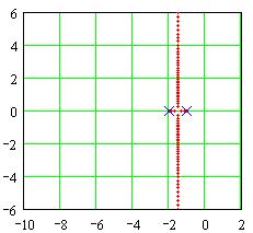
| Consider adding a lead compensator to a system with two open loop poles. The root locus for the uncompensated system is shown at the right. The closed loop poles come together at s = -3 and move vertically. Since faster response will come from poles further into the left half of the s-plane we need to ensure that the closed loop poles are as far left as we need them. Let us assume that we have decided that we need to have the real part of the closed loop poles at -4 or further to the left. We want to design a lead compensator for this system. We will arbitrarily place the zero for the system at z = -3 and then determine the location for the compensator pole. | |
You can play the video by clicking here. It will let you examine the effect of the pole location on the root locus. The video starts with the pole right on top of the zero,
and the pole moves to the left showing how the root locus changes. (If your video plays in the standard media player, click the pause button, then use the slider to adjust the pole location.)(If your video plays full screen, click the page to start the video.)
Copyright 1999 di Luna